Guide to Coaxial Cable Theory for RF Applications
When we design telecommunications systems we consider a large number of factors - beamwidth, bandwidth, carrier frequency, Fresnel zones, intermodulation, the list goes on.
On the other hand - when it comes to cabling, we really only need to compare the strength and quality signal - that is, the signal that goes in, to the signal that comes out.
Coaxial Basics
Transmission of DC over a physical medium requires two conductors to complete the circuit - the 'go' wire, and the 'return' wire.
When it comes to RF transmission, the coaxial cable becomes a type of transmission line, the go wire takes the form of a centre conductor, and the return wire, known as the outer conductor, consists of an electrical shielding that surrounds the centre conductor.
Because RF is a form of high frequency alternating current (alternating literally millions of cycles faster than typical electrical transmissions), their wave nature must be taken into account when designing cables.
Unshielded open wire cables, such as those used in the electricity grid, are suitable transmission lines for applications in which the frequency iands low enough that power is not lost through the generation of radio waves.
When it comes to RF transmission, unshielded cables will not only lose power through the generation of radio waves, but also have spurious transmissions induced upon the wire from nearby sources of electrical interference.
The basic concept behind coaxial cables uses the return wire as a shielding mechanism, resulting in the electromagnetic field existing only between the inner and outer conductors.
Centre Conductor
The centre conductor of a coaxial cable is used to transfer the AC signal, and often comprises of either a solid copper wire or multiple strands of twisted copper wire.
Multi-strand centre conductors are much more flexible than their solid copper counterparts, but incur significantly more signal loss per metre of cable (known as attenuation) due to the Proximity Effect.
The diameter, or more importantly, the surface area of the inner conductor is also critical in reducing Ohmic losses via the Skin Effect.
While multi-strand conductors have a larger surface area than solid core cables, at the high carrier frequencies employed by 3G and 4G communications the Proximity Effect causes greater losses than those of the Skin Effect - this principle is why you don't see Litz wires used for AC transmissions above about 1MHz.
Dielectric Insulator
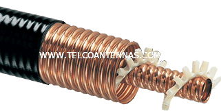
The dielectric insulator is used to separate the centre conductor from the outer conductor while at the same time minimising Ohmic losses arising from contact with the conductors.
In order to minimise signal loss, dielectrics often consist of aerated materials such as foamed polyethylene, PTFE, or in high power communications supporting structures such as spirals, rectangular boxes, and stars are used to approximate an air dielectric.
The perfect dielectric insulator would comprise of an inert gas or vacuum. The dielectric must not only isolate the two conductors, but in order to achieve a constant impedance it must separate them at a specific distance. We'll talk about impedance later on.
Outer Conductor
The outer conductor of a coaxial cable is kept at ground potential and provides electromagnetic shielding - isolating the inner electromagnetic signal from external interference and restricting signal power to the confines of the dielectric.
Commonly the outer conductor takes the form of a metal wire braiding and while this affords greater flexibility, gaps between the wires result in RF leakage and interference. To circumvent this effect, high grade cables will often be dual shielded with a metal foil such as APA or Aluminium tape.
Cable specifications will often give a percent braid coverage to give a comparative metric of the shielding effectiveness.
Outer Jacket
A coaxial cable's outer jacket doesn't have any electrical function, it is simply provides protection from the elements. Common materials include PVC and polyethylene.
Useful Definitions
A brief explanation of common coaxial cable terms.
Attenuation
Signal power loss measured in decibels per metre (dB/m).
Attenuation comprises of all loss mechanisms, the most prominent of which is Ohmic losses in the conductor and dielectric.
In coaxial cable, the dielectric medium touches the centre conductor and absorbs some of its energy, hence the less dielectric making contact with the copper results in lower attenuation.
In high power communication cables the dielectric insulator often comprises of air-gapped spacers or star/rectangle structures designed to minimise contact with the conductor.
Impedance
Characteristic impedance of a coaxial cable is determined by the spacing between the inner conductor and the outer conductor - or more specifically, the ratio of the outside diameter of the inner conductor to the inside diameter of the outer conductor. The main function of the dielectric insulator is to maintain this constant distance.
Common impedances are 50Ω, 75Ω, and 95Ω.
Capacitance
Capacitance is a property of a conductor in which permits the storage of electrical charge when a voltage or potential difference exists between two conductors.
Since it takes a specific amount of time for a cable to reach its charged level, this interferes with the signal being transmitted.
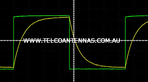
Digital signal modulation results in thousands of sudden changes in voltage in the form of square waves, however capacitance can result in skewing and appearing more like sawtooth waves. Capacitance is given in picofarads per metre (pF/m).
Velocity of Propagation
Often referred to as 'Velocity' or 'VF', velocity of propagation refers to the ratio of the speed of a wave through a physical medium against the speed of light in a vacuum. This metric is used to calculate propagation delay, and is often around 85% for high quality coaxial cables.
Further Reading