Extending StarLink Satellite with Point-to-Point Wireless Bridge - Ubiquiti
Setting Up the Ubiquiti NanoBeam Radios
With the arrival of StarLink Satellite systems delivering a new internet experience through Low Earth Orbit Satellites your choice for your internet access has increased.
The StarLink system comes with a satellite dish and WiFi router and delivers users with a great internet experience when the dish has a clear view of the sky.
You can visit this site to get further information on the StarLink system:
You will need to order your StarLink system directly from the Company. Be sure to include the optional ethernet connector for the StarLink router
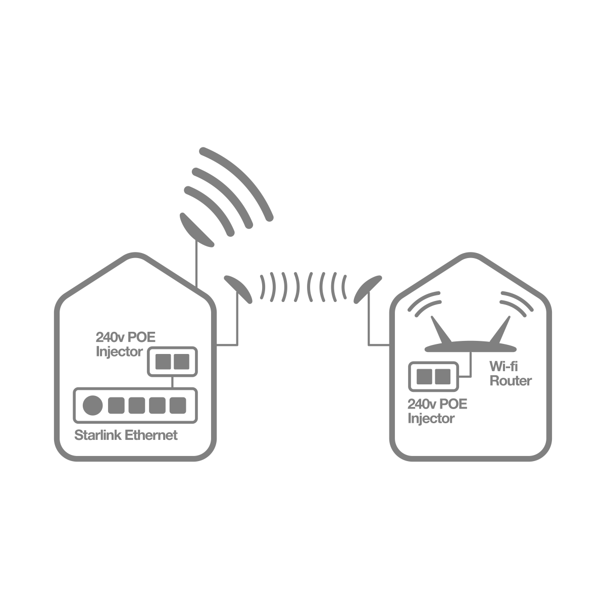
This document will focus on extending access it the internet through the satellite system beyond your Home or Residence outside the range of the Standard WiFi Router through Point-to-Point radio systems to provide a secondary WiFi link at your Shed, Granny Flat or another nearby Home.
The StarLink equipment will need to be ordered directly from StarLink via their web site. The order will need to include an optional ethernet adaptor.
The StarLink dish will need to have clear access to the sky as per the following instructions indicated by StarLink:
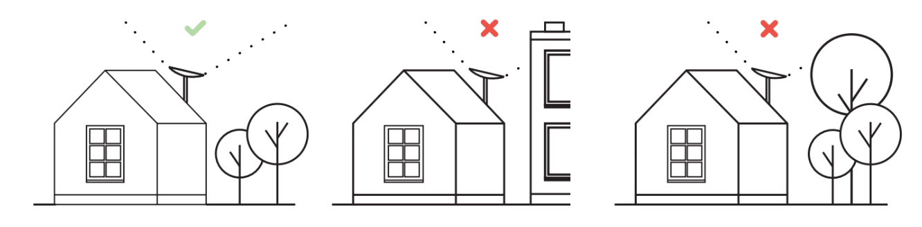
Diagram 2: Starlink Dish Installation Requirements.
The StarLink extension kit will include the following:
- 2 x Ubiquiti NanoBeam Gen2
- 2 x Ubiquiti Universal Antenna Mount
- 2 x WildCat Cat6 UV Rated Outdoor Ethernet Cable
- 2 x Cat6 Indoor Ethernet Cable
The remote end will need a self-supplied WiFi router, or an optional Access Point can be supplied:
Setting Up the Ubiquiti NanoBeam Radios
The Nano Beam Radios come with a Power over Ethernet (PoE) supply. The PoE plugs into any 240V power outlet.
The Radio Unit then has the Outdoor Rated Cat6 Ethernet Cable connected between the radio’s ethernet port and the PoE labelled port on the PoE unit.
The LAN port on the PoE unit is then connected to the StarLink ethernet port and at the other end the WiFi router or optional Access Point via the Indoor Rated Cat6 Ethernet Cable.
Refer to the Diagram 1 for further detail.
Primary Site Radio – StarLink End (Access Point)
Configuring the NanoBeam radio units is best done prior to installation and can be tested prior to final installation. If you are not comfortable configuring the Radios, the team at Telco Antennas can provide this service prior to shipping and an optional extra.
You will need a computer with an Ethernet Port and s a static IP address of 192.168.1.2 in order to complete the configuration.
Connect an ethernet port from the PC to the LAN port on the PoE. Then another ethernet cable to the NanoBeam and to the PoE port on the PoE unit.
Turn the PoE on.
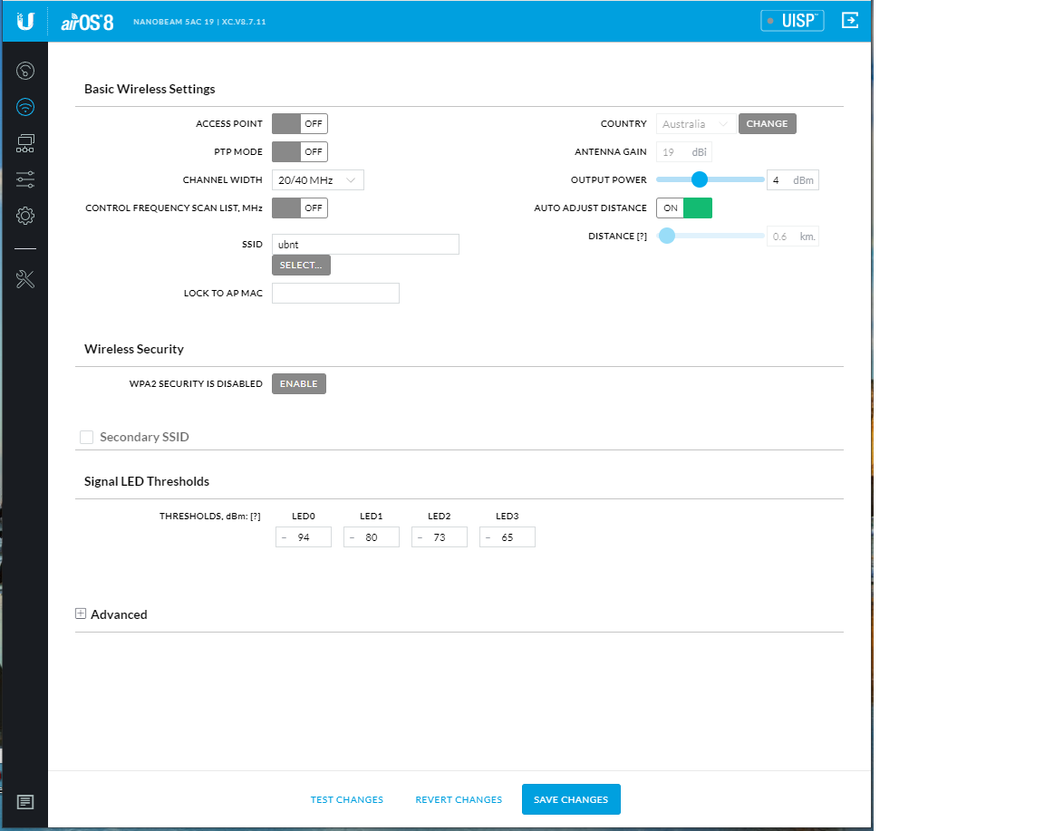
After the unit initialises, open a web browser on the PC and in the address bar type: 192.168.1.20 and the following screen will show:
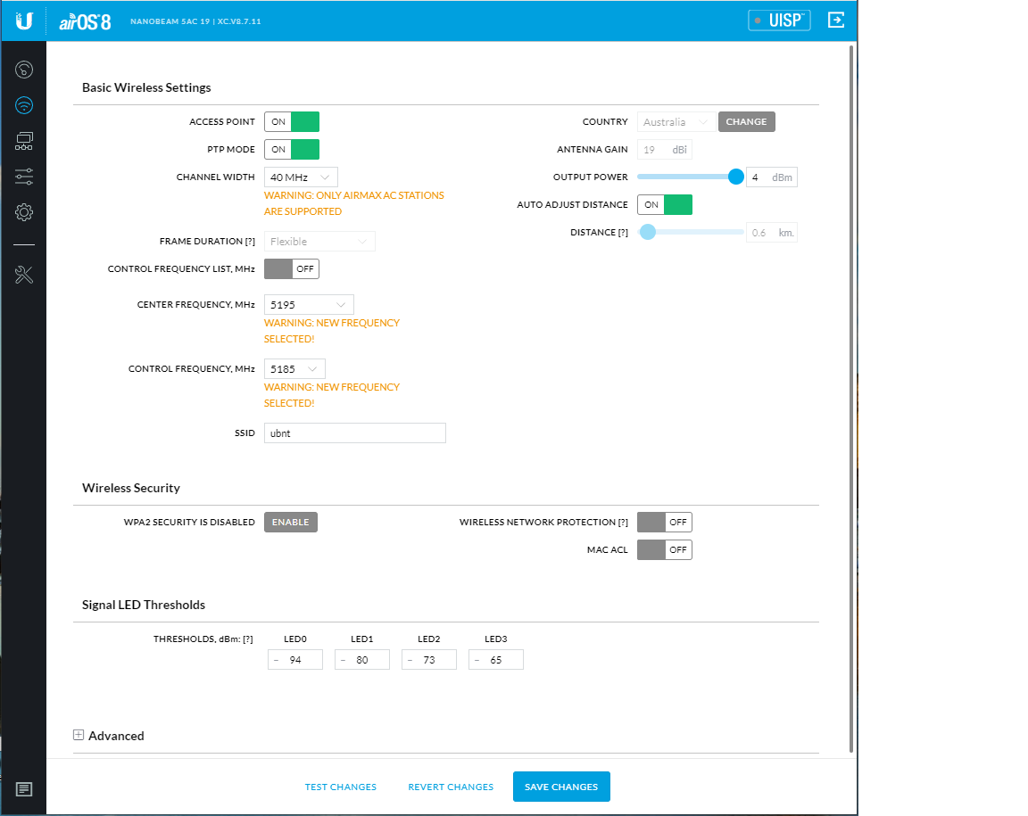
You will need to turn on:
- Access Point Mode, and
- PtP Mode
Next, Click on the “Enable” button for the wireless security:
![]()
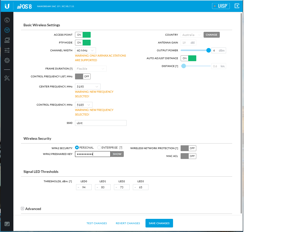
Type in a wireless security password and note this down as you will use the same password for the other radio provisioning.
Next, Click on the “Network” icon in the upper left-hand column:
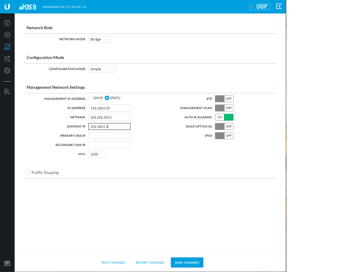
On this screen you will need to make the following changes:
- “Ip Address” – 192.168.0.20
- “Gateway IP” – 192.168.0.1
The Gateway IP is the address of your StarLink router.
Then click on “Save Changes” at the bottom of the page. You will now lose connectivity of the radio as you have changed the IP address.
4.3.2 – Secondary Site Radio – Remote End (Station)
You are now going to setup the second radio, whilst leaving the current one turned on, and change the ethernet cable from the LAN port on the PoE unit for the first radio to the LAN port of the PoE unit for the secondary radio.
After the unit initialises, open a web browser on the PC and in the address bar type: 192.168.1.20 and the following screen will show after setting to country code:
Following the path of the first radio you will set the following:
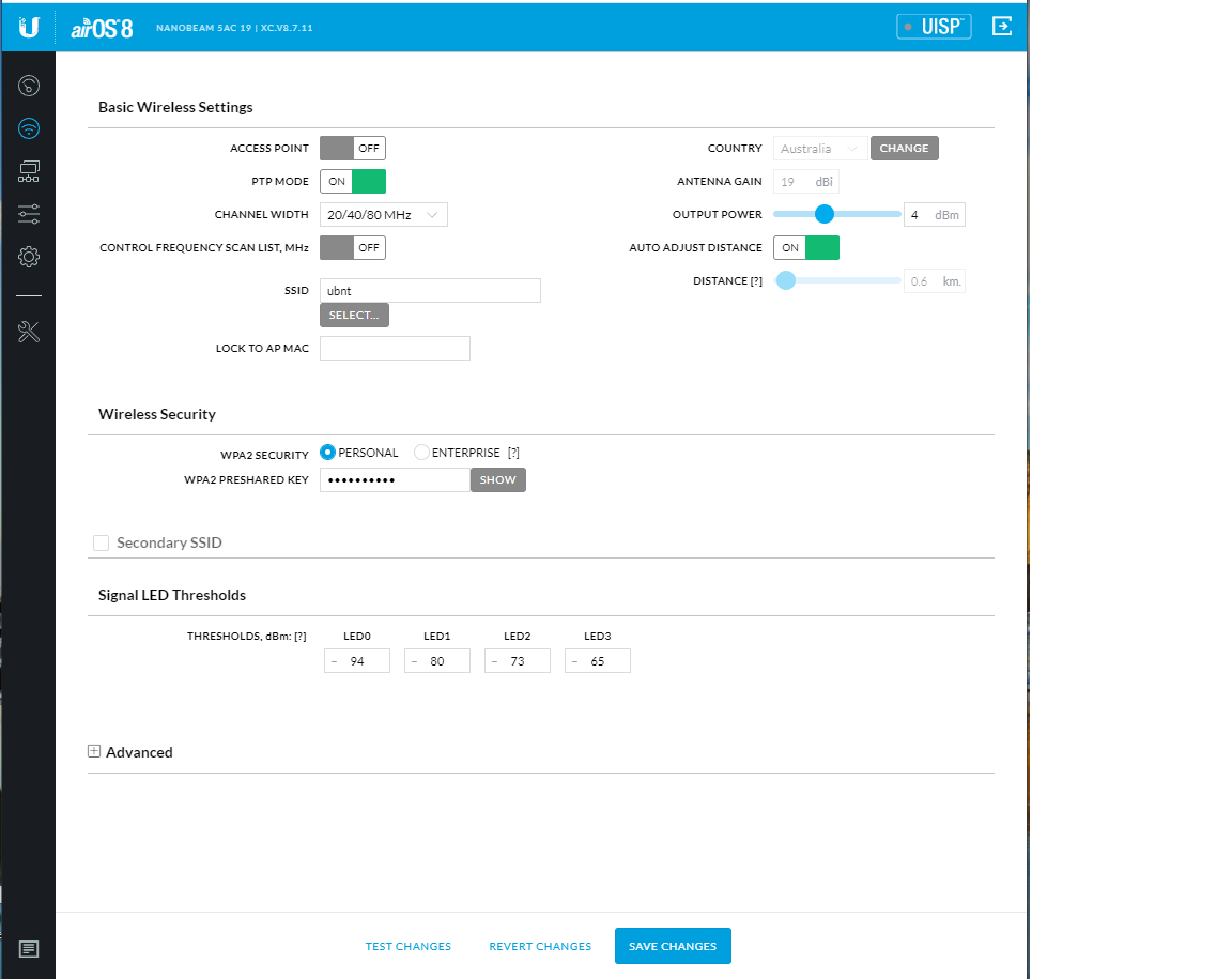
For this screen:
- Turn the PtP button on leaving the Access Point off.
- Enable WiFi and type in the password that is the same as the password for the first radio
- Then click on the Network Icon on the left-hand side for the following screen:
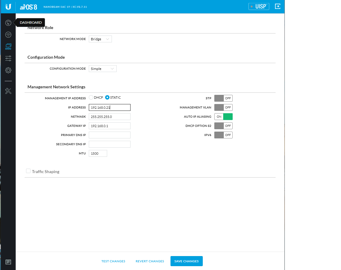
On this screen you will need to make the following changes:
1. “Ip Address” – 192.168.0.21
2. “Gateway IP” – 192.168.0.1
Then click on “Save Changes” at the bottom of the page. You will now lose connectivity of the radio as you have changed the IP address.
Firstly, you will need to change the IP address of your computer to: 192.168.0.2
Then in the web browser type the IP address of 102.168.0.21
The following screen should appear:
The link is now ready for final installation.
Mounting the radio units externally can be done professionally or DIY. The main element to consider is the two external radio units need clear line of sight to each other.
Obstructions will at best reduce the throughput and at worst dent the capability for the radio link to be successful. If in doubt, Telco Antennas offers a desktop survey service for the path planning:
Desktop Site Survey - Microwave Link
The following is a guide to the physical installation of the radio links:
The main area of focus will be line of sight to achieve a successful link.:

You will generally need to clear structures and vegetation to achieve a successful link.
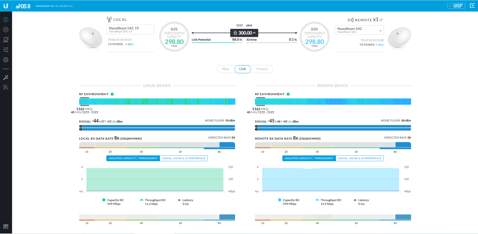
Ubiquiti AC radios comes with an alignment tool in their OS. Go to the Tools icon on the left-hand side and choose “Alignment”.
The following screen shot:
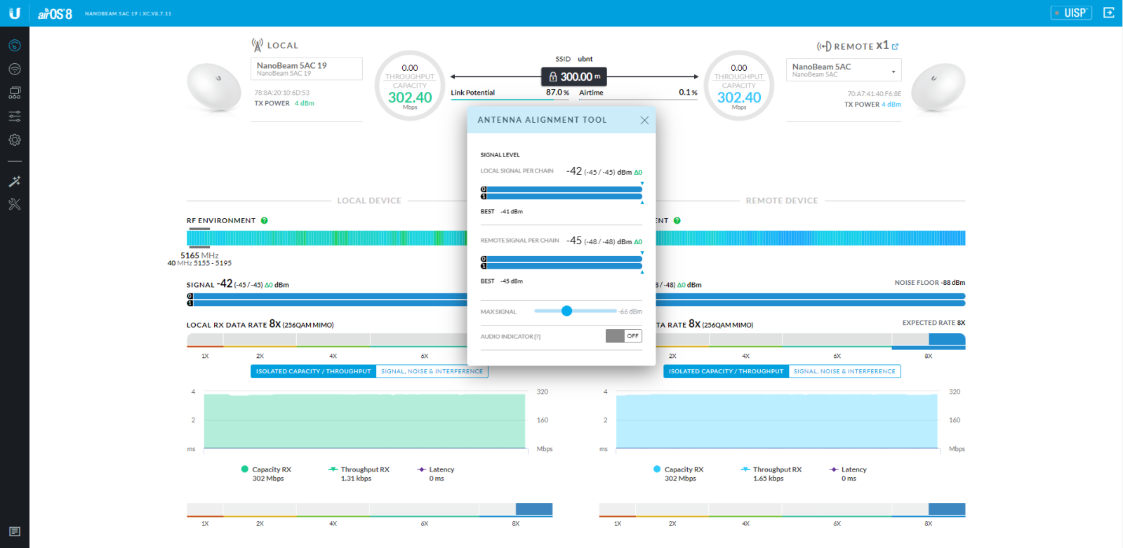
The goal here is to get the “Signal per chain” as close to the same number for the local and remote link.
Once the installation is complete and the StarLink router is connected to the LAN port of the first radio, you should be able to connect to the LAN port of the second radio at the PoE unit and have internet access.
- Check that the power indicator on the NanoBeam is illuminated.
- Check that the main light is on or flashing.
- Ensure there are some or all signal lights are illuminated.
- Can you access the Web user interface on the radios with the assigned IP address?
- Is the PoE unit light on solid. If flashing it could indicate a cable fault.
- The reset button below the ethernet cable on the radio can be pushed in for 10 seconds to factory default the radio to begin the configuration again.
- Are the radios aligned properly and indicated on the status page of the Web User Interface?
- Check the IP addresses are 192.168.0.x
The use of this Document is subject to the following terms:
- The content of the pages on this Document is for your general information and use only. It is subject to change without notice.
- Neither we nor any third parties provide any warranty or guarantee as to the accuracy, timeliness, performance, completeness or suitability of the information and materials found or offered on this Document for any particular purpose. You acknowledge that such information and materials may contain inaccuracies or errors and we expressly exclude liability for any such inaccuracies or errors to the fullest extent permitted by law.
- Your use of any information or materials on this Document is entirely at your own risk, for which we shall not be liable. It shall be your own responsibility to ensure that any products, services or information available through this Document meet your specific requirements.
- This Document contains material which is owned by or licensed to us. This material includes, but is not limited to, the design, layout, look, appearance and graphics. Reproduction is prohibited other than in accordance with the copyright notice, which forms part of these terms and conditions.
- All trademarks reproduced in this Document, which are not the property of, or licensed to the operator, are acknowledged on the Document.
- Unauthorised use of this Document may give rise to a claim for damages and/or be a criminal offence.
- From time to time, this Document may also include links to other Documents. These links are provided for your convenience to provide further information. They do not signify that we endorse the Document(s). We have no responsibility for the content of the linked Document(s).
- Your use of this Document and any dispute arising out of such use of the Document is subject to the laws of Australia.