Guide to Understanding Poor Mobile Network Coverage
What is a Signal Blackspot?
A phone reception or coverage blackspot, is generally defined as a geographic area that experiences reduced mobile phone signal due to factors other than being too far from a cell tower. The user will experience similar issues such as:
-
call drop-outs
-
digital garbling/noise during a call
-
difficulty hearing other caller
-
highly variable signal
-
slow mobile internet
-
internet timeouts
-
increased battery usage.
What causes coverage blackspots?
There are several reasons for coverage blackspots - some are planned for with impacts mitigated/minimised by the network operator, while others are invisible to the network.
To help demonstrate the impact of the different causes, we used a real world cell tower to model performance under different conditions.
Terrain
The number one cause for coverage blackspots is terrain geography.
Radio waves are part of the electromagnetic spectrum - they act the same way light waves do when it comes to obstructions.
We know that moving an object into the path of a light beam causes a shadow, likewise moving an object into the path of radio waves results in a signal shadow - to better understand this, it can help to visualise a cell tower as a powerful spotlight.

When you cast a shadow, the closer the object is to a surface, the crisper its shadow - the further you move the object away from the surface, the fuzzier the shadow.
The cause of this effect is something known as knife-edge diffraction, where a sudden obstruction causes electromagnetic waves to bend inwards to the shadowed region.
If you'd like to understand why this happens, please check out this tutorial on Diffraction.
Coverage simulations
The intensity of light, or in our case RF field strength at any given point along the shadowed region, follows a log-normal process, and for this reason we call signal reduction due to terrain shielding 'log-normal fading'.
The amount a radio wave bends, depends on its frequency - the lower the frequency, the more it will bend (or in terms of a log-normal process - the greater its standard deviation).
In the following images we've run a series of coverage simulations at common frequencies to help visualise the diffraction process.
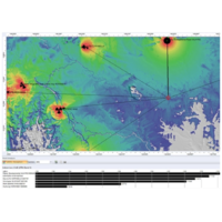
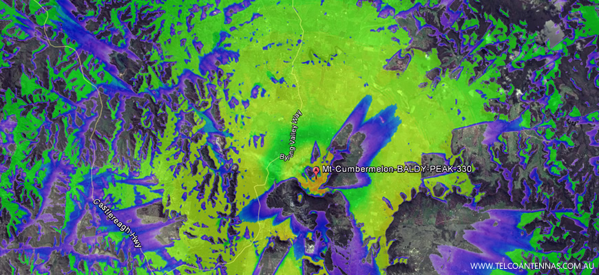
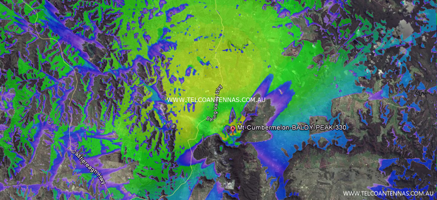
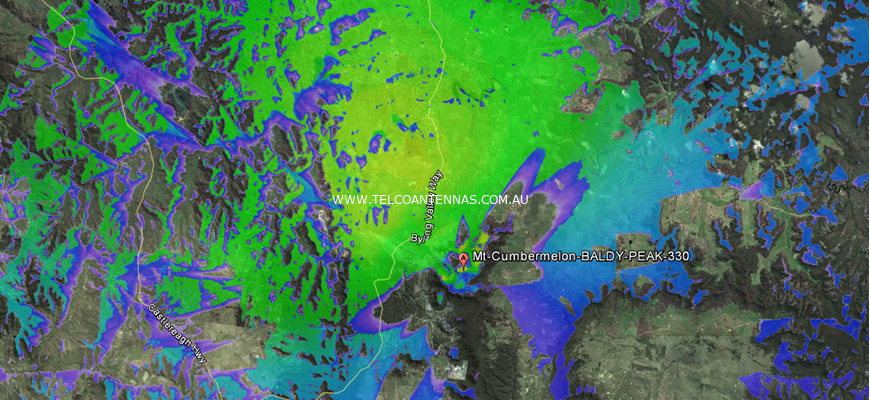
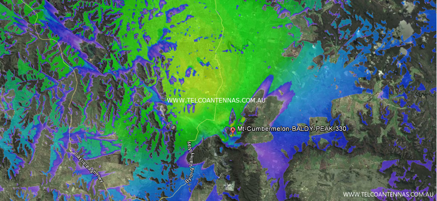
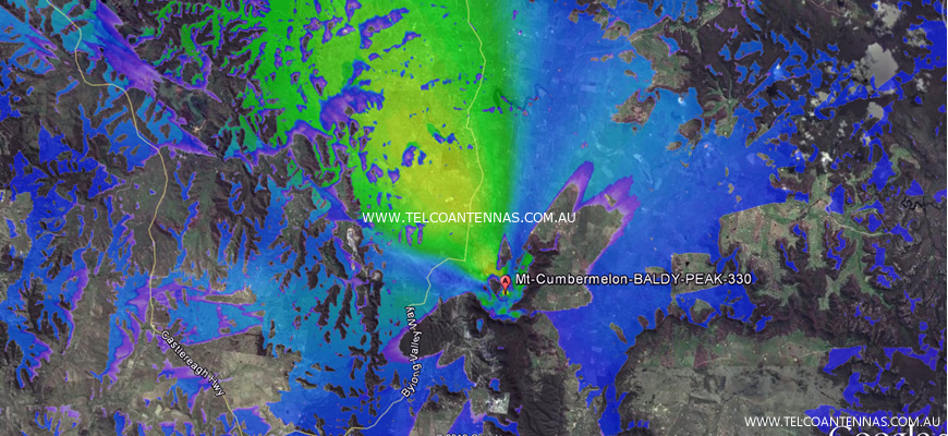
This location is a real Telstra cell tower with a 90 degree (Argus CPX410R) sector antenna transmitting 330 degrees (north north-west).
The four images show 156MHz, 477MHz, 885MHz, and 2147MHz, at identical output powers.
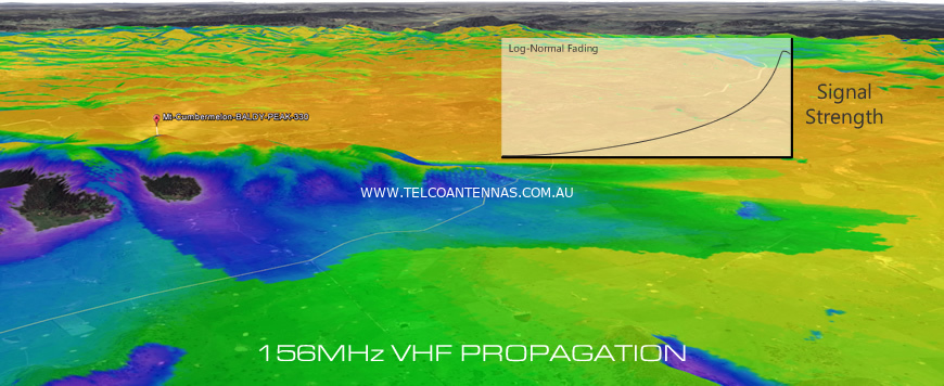
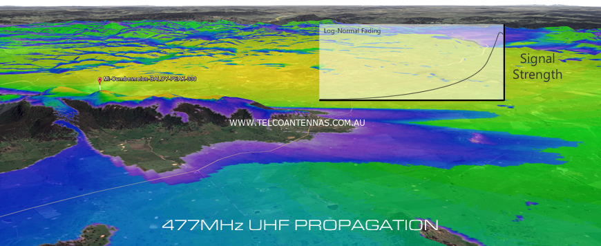
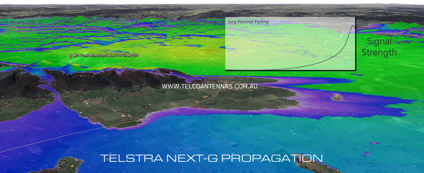
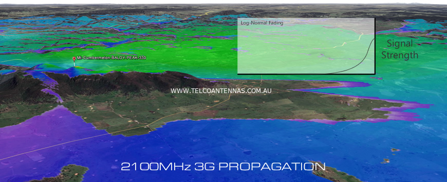
In the images above, a large coverage blackspot is caused by the cell tower's placement, leaving those living at the base of the hill completely without phone coverage.
It's immediately obvious that while the shadowed area stays the same, its effects are minimised by each frequencies level of diffraction.
You might also notice that the lower the frequency the hotter the colours, this is because lower frequencies suffer less 'free space path loss' allowing them to travel greater distances.
This greater coverage distance and reduced log-normal fading are major pushes towards operating 4G networks on lower frequencies like the 700MHz Digital Dividend band recently purchased.
Non-terrain obstructions
Objects along the path of a radio transmission are a big contributor to channel fading.
Physical obstructions such as buildings and trees are the typical culprits, and may act in a similar manner to terrain depending on the material's level of penetrability.
Physical objects also create a multipath environment - transmissions that bounce off objects at an acute angle cause signal reflections (i.e. echos) called multipath signals.
Having travelled a further distance than a straight line transmission, these signals are delayed (longer propagation delay), and to a simple receiver would be nothing more than interference.
However, thanks to clever technology used in cellular communications, multipath signals can be recovered by a RAKE combiner.
RAKE
To digress quickly, a RAKE receiver consists of a series of sub-radios which read the incoming signal at different delay periods (typically one chip in WCDMA), and then combine to result in a higher quality signal.
Unfortunately not all delayed signals can be successfully reinterpreted - if the phase delay is within chip (or within the RAKE's finger) the signal will become interference.
Those of us operating mobile devices inside buildings or behind the cover of dense trees owe a great deal of thanks to our device's RAKE receiver.
Of course the best method of combating the impact of multipath is to relocate our device's antenna to a position that is less impacted by path obstructions. This can often be as simple as trialling a few different positions - for example, consider moving your roof antenna just a few metres either side and reassess signal quality (through RSCP, RSRP, Ec/Io, or SINR metrics).
In-building penetration
You have ample coverage outside your house/office and have poor reception indoors - it's probably a clear indication that the building itself may be the culprit.
Dense or metal-based building materials can reflect or absorb RF signals, reducing the level of signal that reaches indoors.
Unfortunately during building construction, indoor coverage is rarely considered - in fact materials that insulate best and provide most structural strength are typically the worst offenders for reducing indoor coverage.
These materials can include:
-
window insulation/tinting
-
foil-based roof insulation
-
metal roofing (eg. Colorbond)
-
concrete & brick
-
metal support structures
-
large metallic surfaces (eg. Garage Roller Doors)
-
copper plumbing & wiring.
Thankfully due to the presence of a strong signal outside the building, it's usually not difficult to resolve this type of blackspot.
An external antenna is usually positioned on the top of the building with its cable run inside to a smart repeater unit for mobile phones, or patch lead to connect a 3G/4G modem.
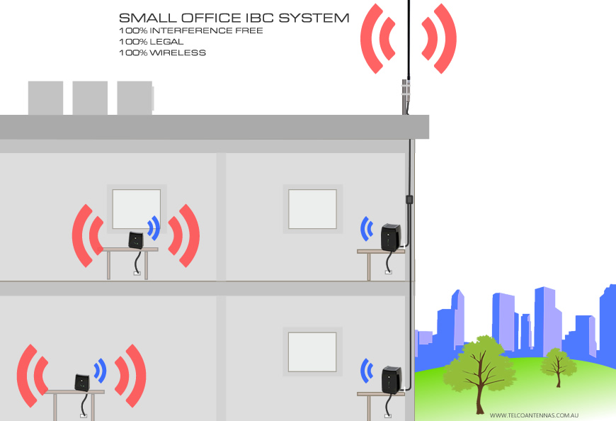
Small to medium sized buildings expand on this principle by using multiple smart repeaters or antennas to extend coverage to mutiple floors or combine several repeater units on one floor to increase capacity.
Larger complexes such as high-rise buildings and shopping centres use a more complicated "Distributed Antenna System" solution, involving a rooftop donor antenna connected into a basement amplifier and optical transfer system, which then routes signal to a series of ceiling antennas.
This type of system involves active amplification and must be licensed and organised through the carrier. It can cost anywhere from $50,000 to $1,000,000 depending on complexity.
For information on organising a carrier-licensed Distributed Antenna System, we encourage you to contact our partner RFI Wireless on 1300 000 734.
Antenna angle and tilt
There are cases where the signal is still weak outside even though the distance to the cell tower isn't too far away and there aren't any major terrain obstructions.
In these cases, the culprit is typically the angling of the broadcasting antenna.
Most rural cell towers use three directional broadcasting antennas, each focusing signal to cover a 120 degree sector.
More basic cell towers only have one omnidirectional transmission antenna that services every user north, south, east, and west (omnidirectional antennas cover the full 360 degree radius).
However, as each transmitter has a capacity limit (in 3G systems each additional user has a negative impact on the allocated radio channel's SINR), having one transmitter covering the entire area greatly limits the number of users and speed available.
Instead, towers that serve a large area or large volume of users have three transmission antennas installed to triple capacity. Intra-cell interference limits the effectiveness of this technique, which is why you typically don't see more than four sectors in operation.
A transmitting antenna can be tilted to face below the horizon to focus their power at a smaller coverage area, creating a micro-cell.
This is often used in high density areas to allow the carrier to pack more cell towers in to a smaller area without causing co-channel interference.
The issue of antenna angling arises when a carrier does not deploy enough sectors to cover off the full 360 degree radius.
Occasionally the carrier may deploy sector antennas favouring a particular direction, providing increased capacity in that direction at a cost of another area.
In other cases the carrier might deploy two sectors along a highway, one facing in each traffic direction to provide longer range and capacity along the path of the highway.
Unfortunately in these cases those on the edge or outside the coverage sector experience diminished signal strength due to the sector antenna focusing transmission power in a different direction.
To help illustrate the reduction in signal strength we've simulated coverage from the most popular types of antenna installed on Telstra cell towers.
Argus CNA010H - Omnidirectional Antenna
Coverage area is the full 360 degrees.
Argus CNPX610R - 120 Degree (Half-Power) Sector Antenna
Approximate coverage sector = 240 degrees. Note the area of reduced coverage to the south.
Argus CNPX410R - 90 Degree (Half-Power) Sector Antenna
Approximate coverage sector = 180 degrees. Note the narrowing of the coverage area, and increased size of blackspots.
Argus CNPX310R - 65 Degree (Half-Power) Sector Antenna
Approximate coverage sector = 120 degrees. Further diminished coverage to the south, south-western, and eastern directions.
Argus CNPX210R - 36 Degree (Half-Power) Sector Antenna
Approximate coverage sector = 60 degrees. Dramatically reduced coverage area.
Cell overlap - Co-channel interference
When two cell towers are receivable from one location, a mobile phone may experience reduced overall signal due to an effect called co-channel interference, or sometimes called crosstalk.
Because both cell towers transmit different information on the same frequency band, the combination of the two radio waves makes it difficult for your device to listen in to what one of the cell towers is saying - it's similar to having a conversation in a crowded room.
Techniques are used to mitigate the impact of co-channel interference, LTE for example, uses a clever scrambling mechanism to shift subcarrier frequencies or symbols to reduce the probability of collisions, and in some deployments Inter-Cell Interference Coordination (ICIC) to schedule frequency allocations.
A raised noise floor is to some degree unavoidable, especially on fully loaded cells, however careful cell placement limits the extent of co-channel interference experienced in the real world.
Cell overlap - pilot pollution
In mobile networks, the presence of multiple cell towers causes more than simple co-channel interference.
Each cell tower transmits a uniquely coded pilot signal called the CPICH, which transmits a constant pattern of data at a predefined power, allowing a mobile to decide between towers by measuring signal strength and quality.
The presence of two or more equally dominant cell towers results in your mobile phone or modem hearing equally strong CPICH signals, which can lead to your device constantly swapping between towers (a process coined 'ping pong handoff').